组成原理-lab1难点之流水线

流水线理解笔记

由于在做组成原理实验的时候,碰到了流水线这个概念,感觉什么都不懂,所以从头开始做做试验来理解一下这个概念,其中的Demo来自于重庆大学组成原理实验指导书Lab1,它的作者是

lvyufeng@cqu.edu.cn

我在作者提供的代码、描述的基础上进行了仿真实验,结合个人理解写下了这篇博客,这个博客以实验、代码为基础,根据行为仿真结果来进行讨论。

错误说明

  • 在最终的实现中,rst与流水线的刷新不应融合到一起,流水线的刷新应当用于流水线的部分刷新,而rst应该用于整体刷新。

  • vivado 有相应的免费版本,官网提供免费下载。

环境

顺便吐槽一下这个HEXO,我用typora编辑出来的代码,他给我隔一行隔一行的放,我用makrtext编辑的代码他直接给我搞成一行了,这咋办呢?

使用的环境是Vivado 2019.1 ,如果你也想用这个环境的话,你可以:

  • 去官网买正版(绝对支持)

  • 去网上搜索一波

  • 去淘宝花30买个

简单流水线

先从一个简单的、没有阻塞的流水线开始。

在开始之前,给大家几点建议(个人看法):

  • 装个文本编辑器吧:vivado自带的文本编辑器太难用了, 建议装一个VSC或者sublime。

  • 去复习一下VHDL的基础,熟悉一下什么叫阻塞赋值什么叫非阻塞赋值,以及一些类型之间的区别

下面先看代码:

1
2
3
4
5
6
7
8
9
10
11
12
13
14
15
16
17
18
19
20
21
22
23
24
25
26
27
28
29
30
31
32
33
34
35
36
37
38
39
40
41
42
43
44
45
46
47
48
49
50
51
52
53
54
55
56
57
58
59
60
61
62
63
64

`timescale 1ns / 1ps


module simplePipeline

#(

parameter WIDTH = 100

)

(

input clk,

input [WIDTH - 1 : 0] datain,

output [WIDTH - 1: 0] dataout

)

;


reg [WIDTH - 1 : 0] piprData1;

reg [WIDTH - 1 : 0] piprData2;

reg [WIDTH - 1 : 0] piprData3;


always @(posedge clk) begin

piprData1 <= datain;

end


always @(posedge clk) begin

piprData2 <= piprData1;

end


always @(posedge clk) begin

piprData3 <= piprData2;

end


assign dataout = piprData3;


endmodule

仿真代码:

1
2
3
4
5
6
7
8
9
10
11
12
13
14
15
16
17
18
19
20
21
22
23
24
25
26
27
28
29
30
31
32
33
34
35
36
37
38
39
40
41
42
43
44
45
46
47
48
49
50

`timescale 1ns / 1ps


module simSimplePipeline();

reg clk;

reg [7 : 0]datain;

wire [7 : 0]dataout;


simplePipeline #(8)test1(

.clk(clk),

.datain(datain),

.dataout(dataout)

);


initial begin

clk = 1'b0;

datain = 7'd0;

end

always #5 begin

clk = ~clk;

end


always @(posedge clk)begin

datain = datain + 1'b1;

end

endmodule

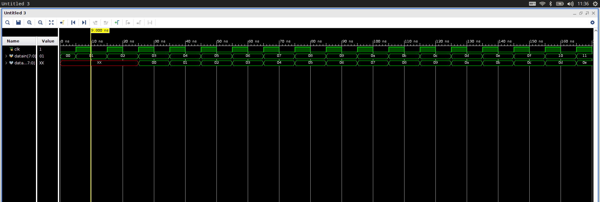
仿真波形图:

代码

这个基础的流水线非常好理解,就是数据传入后,每次检测到时钟上升沿,就将数据进行一次平移,如下图所示:

graph LR

datain -- posedge clk--> piprData1

piprData1 -->|posedge clk| piprData2

piprData2 -->|posedge clk| piprData3

piprData3 --> dataout

可以看到在这个过程中,前三次都需要在检测到时钟上升沿的时候才能够进行非阻塞赋值,而最后一次是连续赋值。

要想理解这个过程,需要明晰一些概念:

  • 连续赋值:带有assign的是连续赋值,如上方代码中的assign dataout = piprData3;连续赋值中赋值符号左方的变量必须是线网类型,这步操作,从硬件的角度理解就是将赋值符号右边与左边进行连线,当右边发生变化的时候,左边立刻发生变化

  • 非阻塞赋值与阻塞赋值

    • 阻塞赋值: [变量] = [逻辑表达式];

    • 非阻塞赋值:[变量] <= [逻辑表达式];

    • 阻塞赋值和非阻塞赋值之间的区别主要在于阻塞,所谓阻塞,阻塞的是当前其他的赋值任务,其中:

      • 阻塞赋值,阻塞了其他的赋值任务,所以表现出的效果就和C中的赋值语句非常相似

      • 非阻塞赋值,没有阻塞其他的赋值任务,所有的赋值都是并行的,想要理解这个,你需要先明确一件事情:用Verilog写代码写出来的是个电路,而非软件

有阻塞的三级流水

代码:

1
2
3
4
5
6
7
8
9
10
11
12
13
14
15
16
17
18
19
20
21
22
23
24
25
26
27
28
29
30
31
32
33
34
35
36
37
38
39
40
41
42
43
44
45
46
47
48
49
50
51
52
53
54
55
56
57
58
59
60
61
62
63
64
65
66
67
68
69
70
71
72
73
74
75
76
77
78
79
80
81
82
83
84
85
86
87
88
89
90
91
92
93
94
95
96
97
98
99
100
101
102
103
104
105
106
107
108
109
110
111
112
113
114
115
116
117
118
119
120
121
122
123
124
125
126
127
128
129
130
131
132
133
134
135
136
137
138
139
140
141
142
143
144
145
146
147
148
149
150
151
152
153
154
155
156
157
158
159
160
161
162
163
164
165
166
167
168
169
170
171
172
173
174
175
176
177
178
179
180
181
182
183
184
185
186
187
188
189
190
191
192
193
194
195
196
197
198
199
200
201
202
203
204
205
206
207
208
209
210
211
212
213
214
215
216

`timescale 1ns / 1ps


module stallablePipeline#

(

parameter WIDTH = 100

)

(

input clk,

input rst,

input validIn,

input [WIDTH - 1 : 0] dataIn,

input outAllow,

output wire validOut,

output wire [WIDTH - 1 : 0] dataOut

);


// pipe1Valid; 代表当前级是否存有有效数据

reg pipe1Valid;

reg [WIDTH - 1 : 0] pipe1Data;

reg pipe2Valid;

reg [WIDTH - 1 : 0] pipe2Data;

reg pipe3Valid;

reg [WIDTH - 1 : 0] pipe3Data;


/*------------------------PIPE1 LOGIC------------------------*/

// 表示pipe1能否被上一级刷新

wire pipe1AllowIn;

// 表示pipe1是否可以用于刷新下一级

wire pipe1ReadyGo;

// 表示pipe1能否进入pipe2

wire pipe1ToPipe2Valid;


// 一旦pipe1的值有效,就可以传给下一个

assign pipe1ReadyGo = 1'b1;

// 如果pipe1中的值已经无效,或者这一轮一定会传给下一个,那么就可以进行接收

assign pipe1AllowIn = ! pipe1Valid || pipe1ReadyGo && pipe2AllowIn;

// 如果pipe1有效,并且pipe1可以进行传输,那么pipe1ToPipe2Valid可以进行。

assign pipe1ToPipe2Valid = pipe1Valid && pipe1ReadyGo;


always @(posedge clk)begin

// 如果需要刷新,那么pipe1Valid 变为0,表示pipe1中的值不再有效

if( rst ) begin

pipe1Valid <= 1'b0;

end

// 不需要刷新,并且pipe1可以进行刷新

// 如果输入端有输入,就代表下一个状态pipe1Valid的值有效

// 如果无输入,就代表下一个状态无效

else if(pipe1AllowIn)begin

pipe1Valid <= validIn;

end

// 如果输入值有效,并且pipe1可以读入,那么就从输入端进行读入

if(validIn && pipe1AllowIn)begin

pipe1Data <= dataIn;

end

end


/*------------------------PIPE2 LOGIC------------------------*/

wire pipe2AllowIn;

wire pipe2ReadyGo;

wire pipe2ToPipe3Valid;


// 一样一样的

assign pipe2ReadyGo = 1'b1;

assign pipe2AllowIn = ! pipe2Valid || pipe2ReadyGo && pipe3AllowIn;

assign pipe2ToPipe3Valid = pipe2Valid && pipe3ReadyGo;


always @(posedge clk)begin

if( rst ) begin

pipe2Valid <= 1'b0;

end

else if(pipe2AllowIn)begin

pipe2Valid <= pipe1ToPipe2Valid;

end

if(pipe1ToPipe2Valid && pipe2AllowIn)begin

pipe2Data <= pipe1Data;

end

end


/*------------------------PIPE3 LOGIC------------------------*/


// 一样一样的


wire pipe3AllowIn;

wire pipe3ReadyGo;


// 一样一样的

assign pipe3ReadyGo = 1'b1;

assign pipe3AllowIn = ! pipe3Valid || pipe3ReadyGo && outAllow;


always @(posedge clk)begin

if( rst ) begin

pipe3Valid <= 1'b0;

end

else if(pipe3AllowIn)begin

pipe3Valid <= pipe2ToPipe3Valid;

end

if(pipe2ToPipe3Valid && pipe3AllowIn)begin

pipe3Data <= pipe2Data;

end

end


assign validOut = pipe3Valid && pipe3ReadyGo;

assign dataOut = pipe3Data;


endmodulepipe1AllowIn

仿真

1
2
3
4
5
6
7
8
9
10
11
12
13
14
15
16
17
18
19
20
21
22
23
24
25
26
27
28
29
30
31
32
33
34
35
36
37
38
39
40
41
42
43
44
45
46
47
48
49
50
51
52
53
54
55
56
57
58
59
60
61
62
63
64
65
66
67
68
69
70
71
72
73
74
75
76
77
78
79
80
81
82
83
84
85
86

`timescale 1ns / 1ps


module simStallablePipeline();

reg clk;


reg rst;


reg validIn, outAllow;


reg [7 : 0]dataIn;


wire [7 : 0]dataOut;

wire validOut;


stallablePipeline #(8)test2(

.clk(clk),

.rst(rst),

.validIn(validIn),

.dataIn(dataIn),

.outAllow(outAllow),

.validOut(validOut),

.dataOut(dataOut)

);


initial begin

// 暂且不刷新

rst = 1'b0;

// 永远可进

validIn = 1'b1;

// 永远可出

outAllow = 1'b1;

clk = 1'b0;

dataIn = 7'd0;),


end

always #5 begin

clk = ~clk;

end


always @(posedge clk)begin

dataIn = dataIn + 1'b1;

end

endmodule

波形图

这个代码看似非常复杂,实际上还是很简实际上还是很简单的,每一层的逻辑都是相似的,每一层与上一层的数据转移是有三个变量进行控制的:

  • pipeXReadyGo:表示当前层的数据能否进入下一层

  • pipeXAllowIn:表示当前层能否接受上一层的数据

  • pipeXToPipeX+1Valid:表示在本时钟周期内,是否会进行传输

我们设计的逻辑如下:

  • 当前层能否进入下一层:始终可以

  • 当前层能否接受:当前层值无效或当前层可以进入下一层,并且下一层可以接收

  • 本次能否转移:本层值有效,并且可以传入下一层

由于我们这样的设计思路,并且allowIn,validOut始终为1,所以我们达到的效果与第一次相同。

简单流水线加法器(8bits 2级流水)

1
2
3
4
5
6
7
8
9
10
11
12
13
14
15
16
17
18
19
20
21
22
23
24
25
26
27
28
29
30
31
32
33
34
35
36
37
38
39
40
41
42
43
44
45
46
47
48
49
50

`timescale 1ns / 1ps


module adder8Bits2Steps

(

input [7 : 0] num1,

input [7 : 0] num2,

// 上一位的进位

input cin,

input clk,

output reg count,

output reg [7 : 0] sum

);


reg countTemp;

reg [3 : 0] sumTemp;


always @(posedge clk) begin

{countTemp, sumTemp} <= num1[3:0] + num2[3:0] + cin;

end


always @(posedge clk) begin

{count, sum} <= {{1'b0, num1[7 : 4]} + {1'b0, num2[7 : 4]} + countTemp, sumTemp};

end


endmodule

这个比较好懂,我就不做过多说明了,但是我想着重讲的是:为什么流水线比普通的看?我们从RTL电路上来看:

上面的是普通的加法器,下面的是流水线加法器,可以看到,对比两者,流水线加法器所使用的寄存器较多。

再看运算速度,对于上面的普通加法器,完成sum1需要等待8个周期,完成sum1后再进行sum0,又需要八个周期,这样就需要16个周期。而对于下面的流水线来说:前四位和后四位的加法同时进行,消耗四个时钟周期,完成后,进行进位,消耗4个周期。所以说,使用流水线可以加快运算。

8Bit 4级流水——无阻塞简单版

一共有四层,所以叫四级流水:

1
2
3
4
5
6
7
8
9
10
11
12
13
14
15
16
17
18
19
20
21
22
23
24
25
26
27
28
29
30
31
32
33
34
35
36
37
38
39
40
41
42
43
44
45
46
47
48
49
50
51
52
53
54
55
56
57
58
59
60
61
62
63
64
65
66
67
68
69
70
71
72

`timescale 1ns / 1ps


module adder8Bits4Steps

(

input [7 : 0] num1,

input [7 : 0] num2,

// 上一位的进位

input cin,

input clk,

output reg count,

output reg [7 : 0] sum

);

reg count1, count2, count3;

reg [1:0] sum1;

// 第一级流水

always @ (posedge clk) begin

{count1, sum1} <= {1'b0, num1[1:0]} + {1'b0, num2[1:0]} + cin;

end


// 第二级流水

reg [3:0] sum2;

always @ (posedge clk) begin

{count2, sum2} <= {{1'b0, num1[3:2]} + {1'b0, num2[3:2]} + count1, sum1};

end


// 第三级流水

reg [5:0] sum3;

always @ (posedge clk) begin

{count3, sum3} <= {{1'b0, num1[5:4]} + {1'b0, num2[5:4]} + count2, sum2};

end


// 第四级流水

always @ (posedge clk) begin

{count, sum} <= {{1'b0, num1[7:6]} + {1'b0, num2[7:6]} + count3, sum3};

end

endmodule

生成的RTL电路图如下:

仿真:

1
2
3
4
5
6
7
8
9
10
11
12
13
14
15
16
17
18
19
20
21
22
23
24
25
26
27
28
29
30
31
32
33
34
35
36
37
38
39
40
41
42
43
44
45
46
47
48
49
50
51
52
53
54
55
56
57
58
59
60

`timescale 1ns / 1ps


module simAdder8Bits4Steps();

reg [7 : 0] num1;

reg [7 : 0] num2;

// 上一位的进位

reg cin;

reg clk;

wire count;

wire [7 : 0] sum;


adder8Bits4Steps test1(

.num1(num1),

.num2(num2),

.cin(cin),

.clk(clk),

.count(count),

.sum(sum)

);


initial begin

num2 = 8'd1;

num1 = 8'd13;

clk = 1'b0;

cin = 1'b0;

end

always #5 clk = ~clk;


endmodule

波形图:

只用了四个周期就算出来了。

8Bit 4级流水——带有暂停刷新功能

在做它之前,我们先来讨论一个问题:为什么需要暂停刷新功能?这是因为不同的指令需要不同的周期,在执行多周期指令的时候,如果cpu不支持动态指令调度和多发射,那么必须停顿

1
2
3
4
5
6
7
8
9
10
11
12
13
14
15
16
17
18
19
20
21
22
23
24
25
26
27
28
29
30
31
32
33
34
35
36
37
38
39
40
41
42
43
44
45
46
47
48
49
50
51
52
53
54
55
56
57
58
59
60
61
62
63
64
65
66
67
68
69
70
71
72
73
74
75
76
77
78
79
80
81
82
83
84
85
86
87
88
89
90
91
92
93
94
95
96
97
98
99
100
101
102
103
104
105
106
107
108
109
110
111
112
113
114
115
116
117
118
119
120
121
122
123
124
125
126
127
128
129
130
131
132
133
134
135
136
137
138
139
140
141
142
143
144
145
146
147
148
149
150
151
152
153
154
155
156
157
158
159
160
161
162
163
164
165
166
167
168
169
170
171
172
173
174
175
176
177
178
179
180
181
182
183
184
185
186
187
188
189
190
191
192
193
194
195
196
197
198
199
200
201
202
203
204
205
206
207
208
209
210
211
212
213
214
215
216
217
218
219
220
221
222
223
224
225
226
227
228
229
230
231
232
233
234
235
236
237
238
239
240
241
242
243
244
245
246
247
248
249
250
251
252
253
254
255
256

`timescale 1ns / 1ps


// 带有暂停与刷新功能的八位四级流水线,散装英语

module adder8Bits4StepsWithStopAndClear

(

input [7 : 0] num1,

input [7 : 0] num2,

// 上一位的进位

input cin,

// 输入是否有效

input validIn,

// 刷新

input rst,

// 暂停

input stop,

input clk,

input outAllow,

// 判断输出是否有效

output wire validOut,

output wire count,

output wire [7 : 0] sum

);

reg count1, count2, count3;


// 记录每一层是否有效

reg pipe1Valid;

reg pipe2Valid;

reg pipe3Valid;

reg pipe4Valid;


// 第一级流水

reg [1:0] sum1;

// 控制变量:和之前的一样

// 表示pipe1能否被上一级刷新

wire pipe1AllowIn;

// 表示pipe1是否可以用于刷新下一级

wire pipe1ReadyGo;

// 表示pipe1能否进入pipe2

wire pipe1ToPipe2Valid;

// 如果没有暂停,那么就可以Go

assign pipe1ReadyGo = !stop;

// 如果pipe1中的值已经无效,或者这一轮一定会传给下一个,那么就可以进行接收

assign pipe1AllowIn = ! pipe1Valid || pipe1ReadyGo && pipe2AllowIn;

// 如果pipe1有效,并且pipe1可以进行传输,那么pipe1ToPipe2Valid可以进行。

assign pipe1ToPipe2Valid = pipe1Valid && pipe1ReadyGo;

// 是否有效

always @ (posedge clk) begin

// 如果需要刷新,那么pipe1Valid 变为0,表示pipe1中的值不再有效

if( rst ) begin

pipe1Valid <= 1'b0;

end

// 不需要刷新,并且pipe1可以进行刷新

// 如果输入端有输入,就代表下一个状态pipe1Valid的值有效

// 如果无输入,就代表下一个状态无效

else if(pipe1AllowIn)begin

pipe1Valid <= validIn;

end

// 如果输入值有效,并且pipe1可以读入,那么就从输入端进行读入

if(validIn && pipe1AllowIn)begin

{count1, sum1} <= {1'b0, num1[1:0]} + {1'b0, num2[1:0]} + cin;

end

end


// 第二级流水

reg [3:0] sum2;

wire pipe2AllowIn;

wire pipe2ReadyGo;

wire pipe2ToPipe3Valid;

assign pipe2ReadyGo = !stop;

assign pipe2AllowIn = ! pipe2Valid || pipe2ReadyGo && pipe3AllowIn;

assign pipe2ToPipe3Valid = pipe2Valid && pipe2ReadyGo;

always @ (posedge clk) begin

if( rst ) begin

pipe2Valid <= 1'b0;

end

else if(pipe2AllowIn)begin

pipe2Valid <= pipe1ToPipe2Valid;

end

if(pipe1ToPipe2Valid && pipe2AllowIn)begin

{count2, sum2} <= {{1'b0, num1[3:2]} + {1'b0, num2[3:2]} + count1, sum1};

end

end


// 第三级流水

reg [5:0] sum3;

wire pipe3AllowIn;

wire pipe3ReadyGo;

wire pipe3ToPipe4Valid;

assign pipe3ReadyGo = !stop;

assign pipe3AllowIn = ! pipe3Valid || pipe3ReadyGo && pipe4AllowIn;

assign pipe3ToPipe4Valid = pipe3Valid && pipe3ReadyGo;

always @ (posedge clk) begin

if( rst ) begin

pipe3Valid <= 1'b0;

end

else if(pipe2AllowIn)begin

pipe3Valid <= pipe2ToPipe3Valid;

end

if(pipe2ToPipe3Valid && pipe3AllowIn)begin

{count3, sum3} <= {{1'b0, num1[5:4]} + {1'b0, num2[5:4]} + count2, sum2};

end

end


// 第四级流水

wire pipe4AllowIn;

wire pipe4ReadyGo;

reg [7 : 0]sum4;

reg count4;

// 一样一样的

assign pipe4ReadyGo = !stop;

assign pipe4AllowIn = ! pipe4Valid || pipe4ReadyGo && outAllow;

always @(posedge clk)begin

if( rst ) begin

pipe4Valid <= 1'b0;

end

else if(pipe3AllowIn)begin

pipe4Valid <= pipe3ToPipe4Valid;

end

if(pipe3ToPipe4Valid && pipe4AllowIn)begin

{count4, sum4} <= {{1'b0, num1[7:6]} + {1'b0, num2[7:6]} + count3, sum3};

end

end


assign validOut = pipe4Valid && pipe4ReadyGo;

assign sum = sum4;

assign count = count4;


endmodule

仿真

1
2
3
4
5
6
7
8
9
10
11
12
13
14
15
16
17
18
19
20
21
22
23
24
25
26
27
28
29
30
31
32
33
34
35
36
37
38
39
40
41
42
43
44
45
46
47
48
49
50
51
52
53
54
55
56
57
58
59
60
61
62
63
64
65
66
67
68
69
70
71
72
73
74
75
76
77
78
79
80
81
82

`timescale 1ns / 1ps


// 测试最后一个模型

module finalSim();

reg [7 : 0] num1;

reg [7 : 0] num2;

// 上一位的进位

reg cin;

// 输入是否有效

reg validIn;

// 刷新

reg rst;

// 暂停

reg stop;

reg clk;

reg outAllow;

// 判断输出是否有效

wire validOut;

wire count;

wire [7 : 0] sum;


adder8Bits4StepsWithStopAndClear test1(num1, num2, cin, validIn, rst, stop, clk, outAllow, validOut, count, sum);

initial begin

num1 = 8'd1;

num2 = 8'd1;

cin = 1'd0;

validIn = 1'd1;

rst = 1'd0;

stop = 1'd0;

clk = 1'd0;

outAllow = 1'd1;

# 30 rst = 1'b1;

# 30 rst = 1'b0;

end

always # 5 begin

clk = ~ clk;

end

always # 10 begin

stop = ~ stop;

end

endmodule

仿真波形图:

30ns时,rst = 1,60ns时,重新将rst置为0,并且,每10ns翻转一次stop

在90ns的时候将rst置为1,并在120ns时,将其置为0,则仿真波形图如下:

validOut正确,如果大家觉得这段结果难以理解,那不是因为你们菜,而是因为我这个测试用例设计的太狗屎了。

下面取消对rst的更改,全程不刷新,只进行周期性stop:

最后,不stop,也不刷新:

算了,再加最后一组,只刷新,不stop:

在最后一组中,可以看出:当刷新被重置为0时,开始重新计算,4个时钟周期后,计算完成,validOut被重新置为1。如果大家还是看不懂,可以copy下来代码,自己跑跑试试,我这个用例造的着实垃圾。